


GODIAG GT107 With Kess V2 Read DQ200/DQ250/DQ500 Connction Diagram
Here is a guide for Godiag GT107 DSG Cable Gearbox Data Read/Write Adapter to read DQ250, DQ200, DQ500 data with KESSV2.
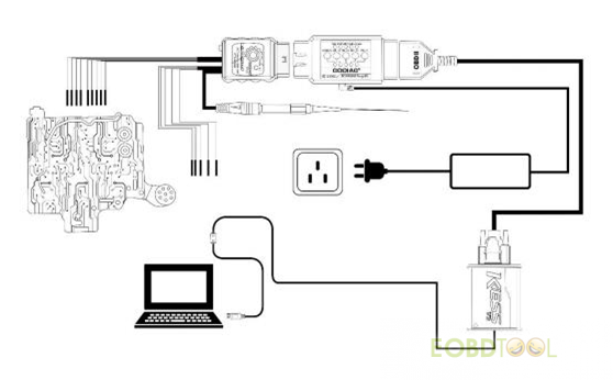
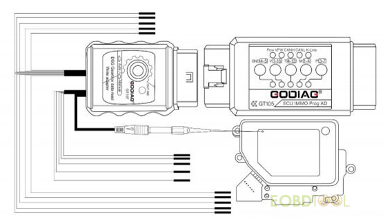
Connection Diagram:
Steps:
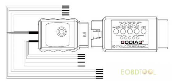
1.Connect Godiag GT107 to gearbox ECU DQ250,DQ200,DQ500.
2.Connect the Godiag ECU IMMO Prog AD with the vehicle battery or 12v 3A power supply.(The Godiag ECU IMMO Prog AD’s IMMO button must be up.)
3.Connect KESSV2 Device,and press down the GT107 switch and it will be in “Manual” ignition mode.
4.Press down the 120 ohm resistor switch.
5.Connect the computer and open the software to read and write data.
Work BOOT: use a direct connection to the connector of the control UNIT, the switching power supply is carried out either manually (recommended) or by using the scheme of automatic powercontrol, GODIAG GT107 DSG gearbox data adapter (same PowerBox or converted from KESS).In case of manual control,the entrance to the boot mode may not happen on the first attempt.
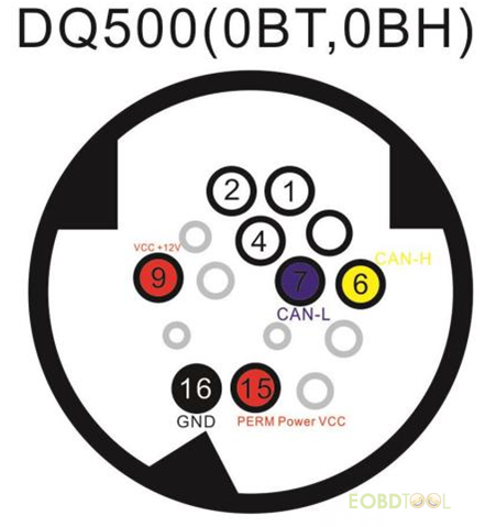
Read DQ500:only when connected directly!
NOTE: the power supply must be switched manually,while only the ignition must be switched on or off(pin 15),the second contact must be connected constantly.
Operation in BSL with VL300/V30: requires drilling a single hole in the minimum diameter cap in order to insert aprobe into it. The probe is connected to the GODIAG GT107 DSG Gearbox Data Adapter BOOT 1k ohm GND line(included in the GT107 host).It is mandatory to connect to-line and it is highly recommended to use auto power to quickly “feel” the pin on the board.The photos below show the drilling location and the pointon the board where the probe should go.
UK Professional OBD2 Tools Online Shop